Display Control Panel
← Back to Flight Deck Overview
Overview
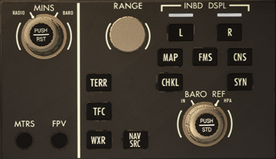
The Display Control Panel (DCP) is used to adjust settings on the Primary Flight Display (PFD), including altitude, barometric reference units, minimums standard, and content on the navigation display. Pilots can use the knobs and buttons to switch between different units and display modes.
Panel Functions
Minimums (MINS) Knob
This is a dual concentric knob:
- Outer knob: Selects the minimums alert mode: Radio Altitude (RA) or Barometric Altitude (BARO).
- RA mode: Increments by 1 ft, range 0 ~ 1000 ft.
- BARO mode: Increments by 10 ft, range -2000 ~ 18000 ft.
- Inner knob: Adjusts the minimums value. Turn clockwise to increase, counterclockwise to decrease.
- PUSH RST button:
- Activates or clears the minimums setting.
- If no value is set and no valid value is received from FMS, the display shows “MINIMUMS”.
- If a value is set or received from the FMS, pressing this button clears the minimums.
Metric Units (MTRS) Button
- Toggles the selected altitude display unit:
- Pressed: Displays selected altitude in meters;
- Pressed again: Reverts back to feet.
Flight Path Vector (FPV) Button
- Pressed: Shows or hides the FPV icon on the PFD.
Barometric Reference (BARO REF) Knob
Also a dual concentric knob:
- Outer knob: Selects pressure units:
- IN (inHg): 0.01 inHg increments, range 22.00 ~ 32.50 inHg;
- HPA (hPa): 1 hPa increments, range 745 ~ 1100 hPa.
- Inner knob: Adjusts current barometric setting.
- PUSH STD button:
- Activates the standard pressure (STD) or selected barometric value;
- If a setting exists, toggles between STD and selected value;
- If no setting, activates STD when pressed.
Range Knob
- Controls the scale of the map display on the MAP format:
- In-flight range options: 5, 10, 20, 40, 80, 160, 320, 640, 1280 NM;
- Taxiing range options: 0.5, 1, 2, 5, 10, 20, 40, 80, 160, 320, 640, 1280 NM.
- If HSI is locked at 40 NM and the DCP group is unavailable (e.g., IDU2 or IDU3 failure), control is reassigned to HSI.
TERR, TFC, WXR Buttons
- These overlay corresponding information layers on the MAP format:
- TERR: Terrain overlay;
- TFC: TCAS traffic overlay;
- WXR: Weather radar overlay.
NAV SRC (Navigation Source) Selection Button
- Switches the navigation source for the HSI in MAP mode.
- Left display sequence: FMS1 → VOR1 → LOC → FMS2 → VOR2 → LOC;
- Right display sequence: FMS2 → VOR2 → LOC → FMS1 → VOR1 → LOC.
- If IDU5 is in full MAP mode, it supports only switching between FMS1 and FMS2.
Inner Display Selector (L/R INBD DSPL) Buttons
- Selects either the left (L) or right (R) center display (IDU2 or IDU3) as the target window.
- When pressed, the white light illuminates to indicate active selection.
- Press again to cancel the selection (light turns off).
- This button does not control EICAS pages.
- If IDU2 or IDU3 fails, display control can be performed using the MFW format buttons below.
Format Selection Buttons (MAP, FMS, CNS, CHKL, SYN)
- Changes the display format for the selected IDU2 or IDU3 target window.
- Must activate the display first using L/R INBD DSPL before selecting format.
- Button functions:
- MAP: Navigation map;
- FMS: Flight management system;
- CNS: Communications/navigation status;
- CHKL: Electronic checklist;
- SYN: Systems synoptic.
Note
If IDU2 (or IDU3) fails and IDU1 (or IDU4) is functional, the corresponding MFW format page will be displayed on IDU1 (or IDU4) automatically.